

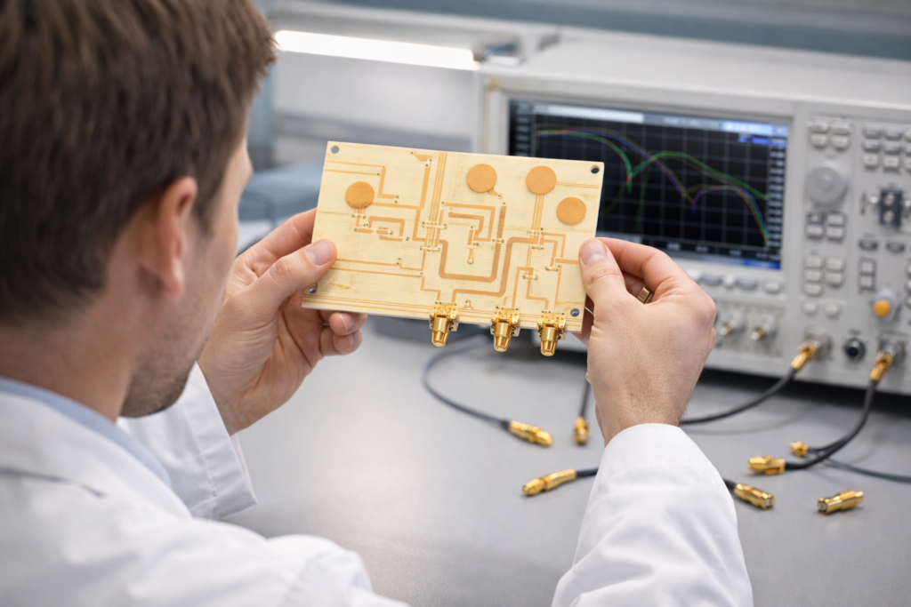
Finding the right high frequency PCB manufacturer takes more careful evaluation than sourcing a standard multilayer board. RF and microwave boards use specialty laminates, require tight impedance control, and depend on process controls that most general PCB factories are not equipped to handle. Choosing a supplier who lacks genuine high frequency capability means boards that do not meet return loss or insertion loss targets, impedance that drifts across the panel, and design iterations that could have been avoided with a better manufacturing partner from the start.
This guide covers the specific questions to ask, the capability claims to verify, the certifications that matter, and the red flags that tell you a supplier is not suited for RF and microwave work. It also covers how to structure your design files and order information so that even the best supplier can do their job correctly.
Why Choosing a High Frequency PCB Manufacturer Is Different
When you order a standard FR4 multilayer board, the critical variables are layer count, trace width, drill size, surface finish, and delivery. These are well-understood, widely standardized processes. Most PCB factories can handle them.
High frequency PCB manufacturing adds a layer of complexity that not every factory can meet. The laminate materials involved, Rogers, Taconic, Isola, and PTFE, require different drilling parameters, different desmear chemistry, different lamination pressures, and more precise etching control than FR4. The finished boards must meet electrical performance specifications, not just dimensional and visual ones. Controlled impedance must be verified by TDR testing, not estimated from a calculation.
A factory that claims to handle Rogers materials but lacks plasma desmear equipment, LDI imaging, or TDR test capability is not actually equipped for serious high frequency production. The difference between a claimed capability and a genuine one shows up in your board performance, not in their quotation.
FastTurn PCB has invested in the specific equipment required for high frequency production: PLASMA processing systems for PTFE and Rogers desmear, Orbotech LDI machines from Israel for fine-line imaging, Ende CNC drilling machines from Taiwan for back-drilling, and BURKLE lamination presses from Germany for multilayer high frequency stack-ups. These are not improvised solutions. They are the tools that high frequency manufacturing actually requires.
The Questions to Ask Before Placing an Order
Before committing to a high frequency PCB manufacturer, ask these questions directly and evaluate the specificity and confidence of their answers.
What high frequency laminates do you stock and process regularly?
A genuine high frequency PCB manufacturer will have Rogers RO4003C, RO4350B, and RO3000 series materials in inventory along with Taconic options and at minimum one PTFE-only laminate. If a supplier stocks only one Rogers material and lists everything else as available on request, their high frequency production volume is low and their process experience with those materials is limited.
FastTurn PCB stocks Rogers RO4003C and RO4350B as standard materials and works with RO3000 series, Taconic TLY and RF families, Isola I-Tera MT40, and pure PTFE laminates for demanding applications. Prototype builds on RO4003C can start within hours of file submission.
What desmear process do you use for PTFE and Rogers materials?
This question separates suppliers with genuine high frequency capability from those without it. PTFE-based laminates cannot be desmeared with the standard potassium permanganate chemistry used for FR4. Sodium etch or plasma desmear is required to prepare PTFE hole walls for reliable copper adhesion. Suppliers who answer this question vaguely or describe only their standard FR4 desmear process do not have genuine PTFE processing capability.
FastTurn PCB uses dedicated PLASMA processing equipment for PTFE and Rogers hole wall preparation. This is non-negotiable for reliable plating on these materials.
What imaging system do you use for fine-line traces?
High frequency PCB traces are often 3 to 5 mil wide on the signal layers, with some designs running to 2.5 mil. Contact film exposure cannot hold the registration and resolution needed for these trace widths consistently across a production panel. Laser Direct Imaging, which uses a UV laser to expose photoresist directly from Gerber data without a physical photomask, is the standard for fine-line high frequency production.
FastTurn PCB uses Orbotech LDI machines, which are among the leading imaging systems available in PCB production. LDI achieves trace width tolerance within plus or minus 0.5 mil and layer-to-layer registration within 25 micrometers.
Do you offer back-drilling for via stub removal?
For multilayer high frequency boards operating above 5 GHz, via stubs in plated through-holes cause resonant notches that can fall within the operating band. Back-drilling removes the unused stub portion of the via barrel after fabrication, eliminating this problem. Not all PCB factories offer back-drilling, and those that do vary significantly in their depth control accuracy.
FastTurn PCB supports back-drilling using their Ende CNC drilling machines, which provide precise depth control for reliable stub removal. If your design operates above 5 GHz on a multilayer stack-up, ask specifically about back-drilling capability and depth tolerance.
How do you verify controlled impedance?
The correct answer is TDR testing on test coupons included in the production panel. TDR applies a fast electrical pulse to a trace and measures the reflected signal to calculate the actual impedance at every point along the trace length. This is the only reliable way to verify that the fabricated trace meets the specified impedance target.
Any supplier who answers this question by describing a calculation rather than a measurement does not verify impedance by testing. Calculation tells you what impedance the trace should have based on the design parameters. TDR tells you what impedance it actually has after fabrication. For high frequency work, only the measurement matters.
FastTurn PCB performs TDR controlled impedance testing on every high frequency order. Test reports are included with shipment. Their tolerance is plus or minus 5 ohms or plus or minus 10 percent.
What certifications do you hold?
ISO 9001 covers quality management system processes across production. ISO 13485 covers medical device manufacturing for customers building RF medical equipment. IPC-A-600 and IPC-6012 cover board acceptance criteria and qualification standards. RoHS and REACH compliance covers material and process environmental requirements. UL certification covers safety for applicable product categories.
FastTurn PCB holds ISO 9001, ISO 13485, UL certification, RoHS, and REACH across their production. For customers in medical, automotive, or defense applications, confirm that the relevant certifications are current and applicable to the specific service you are ordering.
What is your actual turnaround time for prototype builds on Rogers materials?
Turnaround time on Rogers materials at a well-equipped facility depends primarily on whether the material is in stock and how complex your stack-up is. For simple 2 to 4 layer boards on RO4003C or RO4350B with standard specifications, 2 to 3 business days is realistic at FastTurn PCB. More complex multilayer builds with back-drilling or via filling add time. If a supplier quotes 4 to 5 weeks for a Rogers prototype, their production volume with that material is low.
Capability Specifications to Verify
Beyond the questions above, these are the numerical specifications to confirm before placing a high frequency order:
- Minimum trace width and space: FastTurn PCB holds 3 mil trace and space as the production standard for high frequency builds, with 2.5 mil achievable for demanding designs. Confirm the supplier can hold this consistently across the panel, not just at a single point.
- Controlled impedance tolerance: Plus or minus 5 ohms or plus or minus 10 percent at FastTurn PCB, verified by TDR. Any tolerance looser than this may not meet the return loss requirements of sensitive RF designs.
- Minimum drill diameter: 0.15 mm finished hole diameter at FastTurn PCB for plated through-holes. For designs with microvias in HDI plus high frequency combinations, 100 micrometer laser-drilled microvias are supported.
- Board thickness range: FastTurn PCB supports finished board thickness from 0.2 mm to 3.2 mm. Confirm your target thickness is within their capability, particularly for thin substrates used in antenna and filter designs.
- Surface finish options: ENIG is the standard for high frequency boards. Confirm availability of immersion silver for designs where the nickel in ENIG adds unacceptable conductor loss. Confirm hard gold availability if your board has SMA connector pads or edge fingers.
- Back-drill depth tolerance: The precision of stub removal depends on the drilling machine and process control. Ask for the back-drill depth tolerance in millimeters and confirm it is sufficient for the via geometry in your design.
Red Flags That Indicate a Supplier Is Not Suited for RF Work
Some signals during the evaluation process indicate that a supplier should not be trusted with high frequency production regardless of what they claim.
Vague answers to technical questions
A supplier with genuine RF manufacturing experience will answer questions about desmear chemistry, imaging technology, TDR testing, and back-drilling specifically and confidently. Vague answers, redirects to sales materials, or claims that they can handle any material without technical detail are signs of a factory that processes Rogers boards occasionally rather than routinely.
No TDR test reports offered with shipment
If a supplier cannot offer TDR impedance test reports as a standard part of a high frequency order, they are not verifying impedance by measurement. For RF work, unverified impedance means unknown return loss, which means unknown performance in the field.
No plasma desmear capability listed
Plasma desmear is a non-negotiable process step for PTFE-based laminates. A supplier who does not list this equipment specifically in their capabilities and cannot describe when and how they use it cannot reliably plate PTFE via holes.
Unusually low pricing on specialty laminates
Rogers and Taconic materials cost significantly more than FR4. A quote for a Rogers board that is priced at FR4 levels is either using a different material than specified or cutting process steps. Either outcome produces a board that does not perform as designed.
Long lead times on standard Rogers materials
A factory that quotes 3 to 4 weeks for a prototype on RO4003C does not stock that material regularly. Either they are ordering it specially for your job, which extends lead time and suggests low high frequency production volume, or they are routing your order through a subcontractor, which reduces their direct process control.
How to Structure Your Files and Order Information for a High Frequency Order
Even the best high frequency PCB manufacturer can only work with what you give them. These practices ensure your order moves through production without delays from file issues.
Specify your laminate material explicitly
Do not specify FR4 equivalent or RF material in your stack-up document. Name the exact laminate: Rogers RO4003C 0.508 mm core, Taconic TLY-5 1.52 mm, or whatever your design requires. Include the datasheet Dk value you used in your impedance calculations. If you are using a hybrid stack-up with FR4 on some layers and Rogers on others, specify which layers use which material.
Include a complete stack-up document
Your stack-up document should define every layer: layer number, function (signal, power, or ground), copper weight, dielectric material, dielectric thickness, and finished board thickness. For controlled impedance layers, specify the target impedance, the trace geometry you designed to, the reference layer, and the Dk value used in the calculation. This document is the single most important thing you can provide for a high frequency order.
Include impedance test coupons in your Gerber data
TDR coupons are simple straight-line traces routed on the panel edge outside your board outline. Include at least one coupon per controlled impedance specification on each signal layer. Standard coupon length is 150 mm. Include a matched reference trace adjacent to each coupon for differential impedance testing. Without test coupons, the manufacturer cannot perform TDR testing on your specific trace geometry.
Specify back-drill requirements clearly
If your design requires back-drilling, mark the vias that require it in your drill file and specify the stub length to be removed in your fabrication notes. Indicate the target back-drill depth from the relevant board surface and the acceptable depth tolerance. Unclear back-drill specifications are one of the most common causes of errors on high frequency multilayer orders.
Mark controlled impedance traces in your Gerber or ODB++ files
Use a dedicated layer or net name convention to mark the traces that require controlled impedance. This helps the engineering review team identify which traces to check during DFM and which nets to include in TDR coupon generation. Standard practice is to define controlled impedance nets in a separate file or layer within your Gerber package and reference them in your fabrication notes.
Material Selection Reference for Common High Frequency Applications
If you are deciding which laminate to use and want a practical starting point, here is a reference that covers the most common application types:
- Wi-Fi 6E and Bluetooth modules at 2.4 to 6 GHz: Rogers RO4003C or RO4350B are practical choices. Both are in stock at FastTurn PCB and can be prototyped in 2 to 3 days. For cost-sensitive designs with generous loss margins, FR4 is sometimes acceptable at 2.4 GHz.
- 5G sub-6 GHz antenna arrays and RRUs: Rogers RO4003C is the industry standard for this application. Low Dk of 3.55 and Df of 0.0027 at 10 GHz give consistent antenna gain and filter performance across production.
- 77 GHz automotive radar: Rogers RO3003 or RO3006 are commonly specified for the antenna layer. The stable Dk across the automotive temperature range of minus 40 to plus 125 degrees Celsius is critical for radar performance over the product lifetime.
- Ku and Ka band satellite terminals: Rogers RT/duroid or Taconic TLY are used at these frequencies where the very low Dk and Df of pure PTFE laminates are needed. Plasma desmear is mandatory for these materials.
- RF test fixtures and calibration hardware: ENIG surface finish and tight impedance tolerance are the primary requirements. Rogers RO4003C is widely used. Some calibration applications specify immersion silver to minimize surface resistance.
- Microwave filter and combiner networks at 1 to 18 GHz: Rogers RO4003C covers most of this range. Above 10 GHz, RO3003 or Taconic RF laminates with lower Dk reduce the physical dimensions of resonant structures and improve Q factor.
Evaluating a New Supplier Before Your First Production Order
For a first engagement with a high frequency PCB manufacturer, the most reliable approach is to place a prototype order before committing to production. A prototype build reveals actual process capability in a way that no amount of capability documentation or sales conversation can.
When reviewing your prototype boards, check controlled impedance results against the TDR test report, not just against your simulation. Check the board dimensions including the dielectric layer thicknesses using a cross-section. Check the surface finish coverage and uniformity on fine-pitch pads and RF launch pads. Check the via plating quality in cross-section if your design has vias that carry RF signals.
FastTurn PCB includes TDR test reports and a certificate of conformance with every high frequency order. If you want cross-section data for a specific via or layer interface, request it as part of your prototype order. Seeing the actual manufacturing quality before production is the most reliable form of supplier qualification.
Working with FastTurn PCB on High Frequency Projects
FastTurn PCB serves customers across 5G, automotive radar, satellite ground terminals, RF test equipment, medical wireless, and IoT applications. Their high frequency production line supports Rogers, Taconic, Isola, and PTFE laminates, with hybrid Rogers and FR4 stack-ups available for mixed-signal designs.
Every order starts with a free DFM review. Engineers check your stack-up against your material and impedance specifications, verify trace geometry against your Dk calculations, review via structures for stub risk on multilayer builds, and confirm material availability before production begins. Feedback returns the same day for most standard designs.
Prototype builds on RO4003C and RO4350B ship in 2 to 3 business days. Multilayer builds with back-drilling or via filling ship in 5 to 7 business days. All high frequency orders include TDR controlled impedance testing. There is no minimum order quantity.
Certifications: ISO 9001, ISO 13485, UL, RoHS, REACH. Boards inspected to IPC-A-600 and IPC-6012. Assemblies to IPC-A-610 Class 2 or Class 3.
Conclusion
Choosing a high frequency PCB manufacturer comes down to verified capability, not claimed capability. The questions about desmear process, imaging technology, back-drilling, and TDR testing are not formalities. They reveal whether a supplier has the equipment and process experience to produce boards that actually meet your RF performance specifications.
Structure your design files and order documentation clearly. Name your laminate explicitly, provide a complete stack-up document, include TDR coupons, and specify back-drill requirements in writing. A good manufacturer will use that information to produce boards correctly on the first build. A less capable one will struggle regardless of how the order is documented.
To request a quote or get a DFM review for your next RF or microwave board, visit high frequency PCB manufacturer services at FastTurn PCB and upload your Gerber files for a same-day engineering review.
