

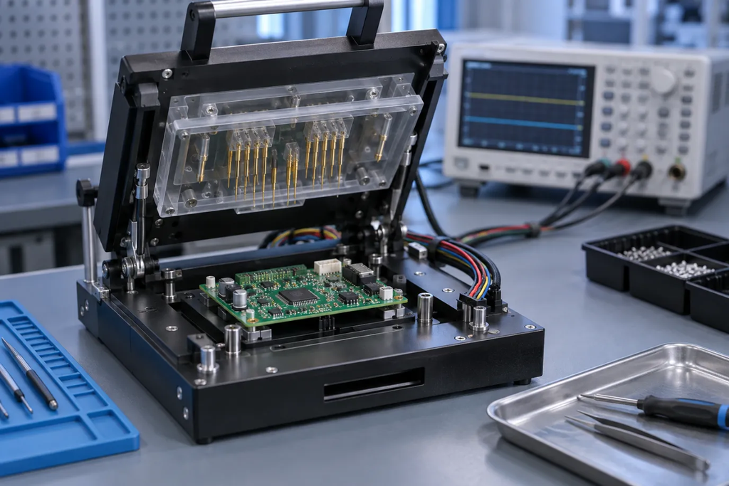
“All boards are tested” sounds reassuring until a failed unit arrives and nobody can explain what the test was intended to detect. A board may have passed optical inspection, a continuity check, or a brief power-on sequence. Those activities answer different questions. None automatically proves that the product performs every required function under every operating condition.
A useful PCB assembly test plan starts with the product’s risks and defines the evidence needed before shipment. It connects likely defects to inspection or measurement methods, identifies what remains outside the scope, and explains how failures are handled. Buyers do not need to become test-equipment specialists to ask good questions. They need to make the meaning of “passed” specific enough that engineering, manufacturing, and quality teams share the same understanding.
Begin with failure consequences and product requirements
List the functions the board must perform and the consequences of getting them wrong. An incorrect indicator light and an uncontrolled power output do not carry the same risk. That difference should influence the attention given to testing, diagnosis, and release decisions. It should also inform which requirements need specialist assessment beyond a routine production test.
Convert broad requirements into observable conditions. “Communications work” is vague. A more useful instruction identifies the interface, configuration, required exchange, and measurable pass criteria. “The supply is stable” similarly needs an operating condition and acceptable limits. These details should come from the product design and validation work, rather than being invented at the factory.
Keep production testing distinct from design qualification. A short manufacturing test screens individual units for selected problems. It does not replace environmental testing, safety assessment, or validation of the design across its intended operating range.
Understand what visual inspection can establish
Manual inspection and automated optical inspection can identify many visible assembly problems, including certain placement, polarity, and soldering defects. Their usefulness depends on visibility, inspection settings, component geometry, and the criteria applied. A component that appears correctly fitted can still be electrically unsuitable or internally defective.
Ask which features are inspected and how the criteria are established. Hidden connections cannot be judged simply by looking at the top of a package. Obstructions, reflections, and component variation can also affect what an optical system sees. Inspection is valuable, but its boundaries should be understood.
Clarify how questionable results are reviewed. A flagged image is not necessarily a confirmed defect, and a human override should have a documented basis. Tracking repeat findings can reveal a process issue even when individual boards are successfully reworked.
Use X-ray where hidden geometry makes it relevant
X-ray inspection can help assess features that are not visible optically, such as certain solder connections beneath packages. It can reveal conditions that warrant further evaluation, but it does not by itself establish complete electrical function. The inspection method and acceptance criteria need to match the package and application.
Avoid a generic rule that every hidden joint is acceptable if an image looks clean. Image interpretation depends on the equipment, viewing approach, and defined criteria. Conversely, a visible feature in an image is not automatically a functional failure. Engineering judgment and the agreed acceptance basis remain important.
For a quotation, state whether the relevant inspection is expected on every unit, a defined sample, or selected assemblies during process setup. Those are materially different scopes and should not be hidden behind a single line saying “X-ray included.”
Separate bare-board testing from assembled-board testing
A bare-board electrical test checks the fabricated circuitry against the applicable connectivity information. After assembly, the board contains components and new solder connections, creating a different set of possible failures. Passing the earlier test does not eliminate the need to consider those later risks.
In-circuit testing can evaluate selected electrical characteristics and assembly conditions through available access. The achievable coverage depends on the design, test strategy, and equipment. It should not be assumed that every component can be independently measured in every circuit; parallel paths and device behavior can complicate measurements.
When reviewing PCB assembly inspection and testing options, ask for a description of the proposed coverage rather than a list of machine names. Equipment availability matters, but the useful question is which defects the actual program is designed to detect on this board.
Define functional testing around real operating behavior
A functional test exercises selected board operations with power applied and appropriate inputs or loads connected. Depending on the product, it might check communications, sensor readings, output switching, analog measurements, or current consumption. The test should be repeatable and should not depend on an operator’s subjective impression.
Provide expected results and allowable limits. For example, a communications test can require a specified command and response sequence, while an analog test can compare readings against an approved stimulus. The exact limits belong to the design owner and should account for the intended measurement method.
Be explicit about exclusions. A room-temperature test at one supply condition does not demonstrate behavior across the entire temperature or voltage range. A board-level test may also omit problems introduced by the final enclosure, cables, or system software. Stating these boundaries prevents a production screen from being mistaken for full product validation.
Design access before the layout is frozen
Test access is easier to provide during layout than after the board has entered production. Discuss the required electrical nodes, programming connections, fixture contact areas, and mechanical support with the test team. A theoretically useful test point is not useful if the fixture cannot reach it reliably.
Consider nearby components, board flex, connector life, and access after any coating or mechanical assembly. Small design changes can sometimes improve repeatability or simplify a fixture, but they should be reviewed alongside electrical and mechanical requirements. Testing should not introduce new damage or compromise product performance.
Ask who approves the test-access review. If the designer assumes the assembler will solve it later and the assembler assumes the test pads are already sufficient, the gap may remain undiscovered until fixtures are being built.
Control firmware, programming, and unique data
An assembled board may need firmware before it can complete a functional test. Identify the approved file, version, programming method, and verification step. Where appropriate, record a checksum or another controlled identifier so a similarly named file cannot silently replace the intended release.
Serial numbers, calibration values, and device-specific credentials require their own handling rules. Define who generates them, how they are assigned, and how duplicate or incomplete programming is detected. Sensitive material should be distributed through an approved process rather than embedded casually in a general manufacturing email.
If test firmware differs from shipping firmware, specify the sequence and final verification. A board that passes with diagnostic software but ships with the wrong application image has not met the delivery requirement.
Build a coverage matrix that exposes the gaps
A simple matrix can connect each important risk or requirement with a method, pass criterion, frequency, and retained record. It makes overlap and missing coverage easier to see. The purpose is not to produce impressive paperwork; it is to make test decisions reviewable.
| Item to assess | Possible method | Decision that must be defined |
| Visible placement and solder conditions | Optical or manual inspection | Applicable criteria and review process |
| Selected hidden solder features | X-ray inspection | Coverage and package-specific criteria |
| Selected electrical assembly conditions | In-circuit or other electrical testing | Accessible nodes and measurable limits |
| Required board operation | Functional test | Inputs, loads, sequence, and pass limits |
| Correct software configuration | Programming verification | Approved release and verification evidence |
The methods in this table are examples, not a mandatory recipe. A simple board and a complex mixed-signal assembly may justify different combinations. The chosen plan should explain both what is covered and what is intentionally left to another stage.
Define what happens after a failure
Specify how failed boards are identified, segregated, diagnosed, and released after rework. A repeat test can confirm that a symptom disappeared, but it does not automatically explain why the first test failed. Intermittent results may indicate fixture contact problems, unstable test conditions, or a real product issue.
Retain enough information to distinguish those possibilities. Useful records can include board identity, hardware revision, software version, test-program revision, measured results, failure codes, and disposition. The required depth depends on the product and contractual obligations.
For a turnkey PCB assembly project, assign one clear owner for coordinating failures that could involve components, fabrication, assembly, or software. Commercial coordination can simplify communication, but engineering approval should remain with the people authorized to make product decisions.
Approve the test process before relying on its results
Run the proposed procedure on representative hardware and review repeatability before treating it as a production gate. Confirm that the setup, connections, software, and instructions produce consistent outcomes. If known-failure samples or controlled fault simulations are appropriate, use them under an agreed engineering plan to challenge the intended detection methods.
Review test time as well as coverage. A slow manual step may be acceptable for a pilot build but become a bottleneck later. Any effort to shorten it should preserve the agreed detection purpose rather than simply deleting inconvenient checks.
A good test plan allows a buyer to ask “Why did this board pass?” and receive a precise answer. That answer should identify the revision tested, conditions applied, requirements checked, and evidence retained. Once those details are defined, testing becomes a meaningful release decision instead of a reassuring but ambiguous promise.
