

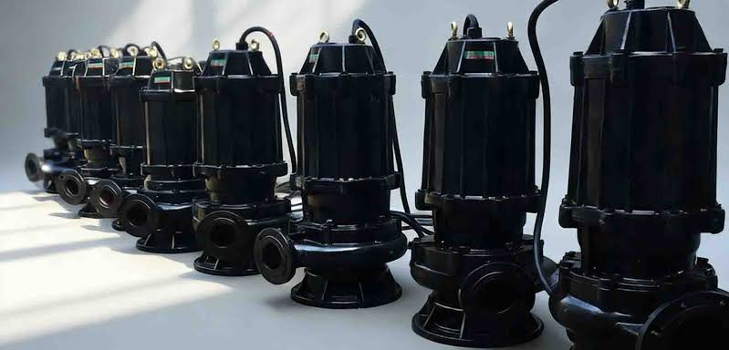
Introduction: Why an Inline Sewage Pump Fails Silently—and Costs You More Than a Replacement
An inline sewage pump looks structurally simple: a vertically mounted centrifugal pump with co-linear suction and discharge ports, directly bolted into piping in the same way as a valve. Unlike clean-water inline circulators, it is designed to handle raw sewage, solid-laden greywater and fibrous waste, commonly deployed in below-grade sumps, basement drainage systems and packaged lift stations.
This equipment rarely suffers sudden, catastrophic failure. Most faults develop gradually: progressive clogging, intermittent loss of prime, overheated mechanical seals and elevated operating current, which eventually lead to motor winding burnout. By the time basement flooding or system alarm tripping occurs, the underlying fault has typically persisted for weeks.
This article provides plant engineers, MRO purchasers and specification consultants with a systematic diagnostic framework. It covers the definition, core components and impeller types, working principles of inline sewage pumps, seven typical failure modes with step-by-step troubleshooting and repair solutions, a field diagnostic grid, applicable industry standards, and a pre-purchase specification screening guide to avoid incorrect equipment selection. Read on to learn more about reliable inline sewage pump operation and maintenance best practices.
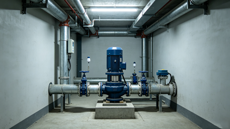
Part 1 — What Is an Inline Sewage Pump? (The Line-Bore Integrity Principle™)
An inline sewage pump is a single-stage, single or double-suction vertical centrifugal pump with co-linear inlet and outlet flanges (consistent horizontal centerline) and identical nominal pipe diameters in most cases. Equipped with non-clog or semi-open impellers (single-vane, double-vane or vortex type), it is specially engineered to pass solid particles and fibrous impurities in municipal and industrial wastewater. The pump, motor and seal flush system (if equipped) adopt close-coupled or back-pull-out structures, installed on a shared base or directly connected to pipelines.
The core reliability of inline sewage pumps is defined as The Line-Bore Integrity Principle™ in professional specification applications. Stable and fault-free operation relies on three key alignment integrity standards; any failure will trigger corresponding typical faults, as shown in the table below:
| Integrity Layer | What Must Hold | Failure Symptom if Broken |
| Hydraulic Alignment | Fully flooded inlet or sufficient NPSHa; no air entrainment caused by unreasonable suction pipeline layout | Cavitation noise, random prime loss, fluctuating flow rate |
| Mechanical Concentricity | Accurate pump-motor shaft alignment (coupled or close-coupled); bearing assembly within tolerance range | High-frequency vibration, bearing overheating, mechanical seal failure |
| Solids-Passage Geometry | Impeller passage meets specified solid passing size (e.g., 50 mm / 2″) with professional fiber handling gap design | Recurrent clogging, rising operating current, impeller fiber wrapping |
Source: ANSI/HI 2.1-2.5 (Centrifugal Pump Standards); EN 12050-1 (Wastewater Lifting Plants)
Inline sewage pumps are distinctly different from submersible sewage pumps (fully immersed in wet wells) and ordinary clean-water inline circulators (closed radial impellers with no solid passing capacity). Applying clean-water inline pumps to sewage treatment scenarios is a common and costly specification error.
Part 2 — Key Components of an Inline Sewage Pump & Their Design Function
2.1 Pump Casing (Volute or Vortex Chamber)
Function: Collects fluid flowing out from the impeller periphery and converts velocity head into pressure head to realize sewage transportation. The casing is generally made of cast iron (ASTM A48 Class 30 / GG25) for conventional wastewater, and duplex stainless steel for corrosive waste media.
Design Note: Suction and discharge flanges are co-axial. The casing is equipped with a drain plug and usually an automatic air release port to eliminate internal air accumulation.
2.2 Non-Clog Impeller (Single-Vane / Double-Vane / Vortex)
Function: Transmits kinetic energy to sewage while allowing the passage of spherical solid particles (35–80 mm diameter, varying by pump model) and long fibrous impurities such as hair, rags and wet wipes.
Vortex (Recessed) Impeller: Generates toroidal fluid flow; solids pass through the vortex chamber around the impeller instead of through the impeller runner. It delivers optimal anti-clog performance, with a 10–15% reduction in hydraulic efficiency as a trade-off.
Single / Double Vane Impeller: Features larger flow passages than closed radial impellers, maintaining higher operating efficiency. However, it is slightly more prone to fiber wrapping when handling long fibrous waste.
2.3 Mechanical Seal (Double Seal, Tungsten Carbide vs. Silicon Carbide)
Function: Seals the gap where the shaft penetrates the casing to prevent sewage leakage and external air ingress. Sewage working conditions require abrasion-resistant seal faces (TC/SiC matching pair), and external clean water flush or quenching devices are configured for harsh waste media.
Failure Trigger: Even short-term dry operation will vaporize the lubricating medium on seal faces and cause micro-cracks; solid particle invasion between seal faces will lead to gradual leakage and final seal failure.
2.4 Shaft & Bearings
Function: Transmits motor torque to the impeller. Most inline pumps adopt grease-lubricated deep groove ball bearings with oversized design, adapting to radial thrust generated under off-BEP (best efficiency point) operating conditions.
Critical Tolerance: The total indicator reading (TIR) of shaft runout for standard models is controlled within 0.05 mm to ensure mechanical operation stability.
2.5 Electric Motor (TEFC or Explosion-Proof)
Function: Drives the shaft at rated speed (1450/2900 rpm for 50 Hz power supply, 1750/3500 rpm for 60 Hz). Inline sewage pumps mostly adopt close-coupled installation with foot-mounted or face-mounted induction motors.
Protection Grade: Minimum IP55 for damp underground environments; Ex d/Ex e explosion-proof configuration is required for hazardous areas (Class I Div. 1 / Zone 1) in accordance with IEC 60079 and NEC Art. 500 standards.
Thermal Protection: Built-in bimetallic sensors or PTC thermistors, linked with the motor starter to realize overheating protection and automatic shutdown.
2.6 Back-Pull-Out Frame (Large-Size Models)
Function: Integrates the motor, shaft and impeller into an integral cartridge structure, which can be disassembled independently without dismantling suction and discharge pipelines. This avoids pipeline strain and alignment deviation caused by repeated disassembly and assembly, greatly improving maintenance efficiency.
2.7 Optional Accessories
Flange Guards & Gaskets (EPDM/Viton): Matched according to wastewater chemical properties to adapt to slightly acidic sewage and cleaning chemical components, ensuring sealing reliability.
Vibration Isolators & Baseplate: Eliminates pipeline transmission strain, recommended for rigid fixed piping systems to protect pump alignment accuracy.
Part 3 — Inline Sewage Pump Impeller Types & Typical Specifications
The selection of impeller type directly determines the pump’s solid passing capacity, fiber resistance, operating efficiency and applicable scenarios. The core parameters and application matching rules are as follows:
| Impeller Type | Solid Passage (Typical) | Fiber Handling | Efficiency | Best-Fit Sewage Application |
| Vortex (Recessed) | 50–80 mm (2″–3″) | Excellent (no fiber wrapping path) | Moderate (10–15% lower than vane impellers) | Raw sewage containing rags and wet wipes; municipal lift station bypass systems |
| Single Vane (Non-clog) | 35–65 mm (1½”–2½”) | Good | Higher than vortex impellers | Municipal domestic sewage with moderate solid impurities; building basement drainage |
| Double Vane (Non-clog) | 25–50 mm (1″–2″) | Fair (long fiber wrapping risk exists) | Highest among non-clog impellers | Low-impurity greywater; treated effluent with occasional tiny debris |
| Grinder / Cutter (Pre-stage) | Crushes solids into slurry | N/A (pre-crushing design) | Low (power loss from crushing operation) | Low-pressure sewage pipe network; residential underground small-diameter pipe drainage systems |
Standard Requirements: ISO 9906 Grade 2B or higher hydraulic performance grade; EN 12050-1 mandates a minimum free passage of 40 mm for fecal sewage pumps unless specially specified.
Part 4 — How an Inline Sewage Pump Works (Operating Sequence)
1. Flooded Suction Priming: Most inline sewage pumps adopt flooded suction installation (suction port below the sump liquid level) or self-priming configuration with a foot valve, ensuring the casing is fully filled with sewage before startup to avoid air lock.
2. Motor Startup Operation: The motor electromagnetic field drives the rotor to rotate, and the shaft and impeller operate at synchronous speed (with minor slip loss).
3. Centrifugal Fluid Transportation: Impeller rotation forms negative pressure at the inlet eye, sewage is sucked into the pump body through the inline suction port, accelerated radially, and forms stable fluid flow through vortex or vane driving.
4. Pressure Conversion & Discharge: The volute casing converts fluid velocity head into pressure head, and sewage is stably discharged from the outlet to the gravity sewer or next-stage lifting equipment.
5. Automatic Level Control: Sump float switches or liquid level transmitters control pump start and stop. The pump runs continuously until the high liquid level drops to the low-level setpoint. A 150–300 mm hysteresis difference is reserved to prevent frequent short-cycling.
6. Post-Shutdown Protection: Some control systems are equipped with delayed shutdown functions to ensure complete pipeline fluid evacuation. Matching check valves prevent sewage backflow and prime loss after shutdown.
Part 5 — Seven Common Problems of Inline Sewage Pumps & Step-by-Step Fixes
The following seven faults are sorted by field occurrence frequency in municipal engineering and commercial building drainage scenarios. Each item includes symptom description, root cause analysis, standardized repair procedures and verification standards.
Problem 1 — Pump Runs but Delivers No Water or Severely Reduced Flow (Dry Spin / Air Lock)
Symptoms: The motor operates normally with slightly low current; discharge pressure is close to zero; suction pipeline emits hollow air vibration sound, and no water flows out of the discharge port.
Root Causes: Air accumulation in suction pipeline caused by incomplete venting; air trapped at high points of suction piping; blocked suction filter or foot valve failure; insufficient liquid filling in the pump body after maintenance; reverse rotation of three-phase motor wiring.
Fix Protocol:
1. Verify rotation direction: Jog the uncoupled motor briefly to confirm consistency with the impeller rotation mark; swap any two phase wires if reversed.
2. Eliminate air lock: Close the discharge gate valve, open the casing air release plug, inject clean water or sewage until no bubbles overflow, then tighten the vent plug.
3. Clean suction components: Remove and clean the suction filter/basket, replace damaged perforated parts; inspect the foot valve for leakage and replace invalid components.
4. Verify hydraulic conditions: Ensure NPSHa ≥ NPSHr + 0.5 m safety margin per ANSI/HI 2.3; adjust suction height or sump liquid level if the margin is insufficient.
Evidence Gate: After repair, the discharge pressure reaches more than 90% of the rated curve pressure under the operating current, and record pressure data before and after maintenance.
Problem 2 — Frequent Clogging / Impeller Wrapping (Recurrent High Amp Draw or Jam Trips)
Symptoms: Operating current periodically exceeds FLA (full load amps) or fluctuates abnormally; pump emits fluttering noise with pulsating flow; thermal overload trips frequently, and impellers are wrapped with rags, hair and wet wipes during inspection.
Root Causes: Mismatched impeller type (clean-water closed impeller misused); insufficient solid passage size for waste characteristics; lack of upstream coarse filtration equipment; excessive vortex gap wear beyond OEM tolerance.
Fix Protocol:
1. Implement LOTO (lock-out/tag-out) procedures, disassemble the back-pull-out assembly, and manually clean wrapped impurities on the impeller.
2. Detect impeller clearance: Use a feeler gauge to measure the impeller-casing gap (standard tolerance 0.5–1.5 mm), replace severely worn impellers.
3. Optimize impeller configuration: Replace single/double vane impellers with vortex impellers for fiber-heavy sewage scenarios to eliminate wrapping risks.
4. Add pre-filtration equipment: Install a fixed-bar screen at the sump inlet (bar spacing ≤ 1/2 of pump free passage diameter) to intercept large impurities.
5. Upgrade equipment: Equip grinder pre-treatment devices for scenarios with a large number of wet wipes, and select pumps with EN 12050-1 compliant ≥40 mm free passage.
Evidence Gate: The operating current stabilizes within ±5% of the nameplate FLA, and record impeller model and clearance data in the equipment asset log.
Problem 3 — Excessive Vibration or Noise (Bearing / Coupling / Cavitation)
Symptoms: High-frequency rattle or low-frequency thumping during operation; bearing housing temperature exceeds 75 °C; vibration amplitude > 4.5 mm/s RMS (ISO 10816-3 warning range); accompanied by intermittent seal leakage.
Root Causes: Pipeline strain caused by rigid piping misalignment; loose coupling and inaccurate motor-potor shaft alignment; deteriorated bearing grease or damaged bearings; NPSH deficiency-induced cavitation; unbalanced impeller caused by partial clogging.
Fix Protocol:
1. Eliminate pipeline strain: Loosen flange bolts, adjust pipeline alignment with flexible expansion joints, and re-tighten bolts to standard torque.
2. Precision alignment: Perform dial indicator calibration for coupled pumps, control angular misalignment < 0.05 mm and parallel misalignment < 0.10 mm.
3. Maintain bearings: Manually rotate the shaft to detect jitter and noise; replace deteriorated grease or worn bearings, ensure stable lubrication.
4. Resolve cavitation: Increase suction submergence (minimum 300 mm for non-vortex impellers, 500 mm for vortex impellers per EN 12050); lower suction elbow position to optimize hydraulic conditions.
5. Clean partial clogged impellers and archive fault data.
Evidence Gate: Post-repair vibration ≤ 2.8 mm/s RMS (ISO 10816-3 qualified range); bearing temperature stabilizes below 65 °C after 30 minutes of continuous operation.
Problem 4 — Motor Overload / Trips Breaker on Start or During Run
Symptoms: Thermal overload protection trips instantly on startup or 5–20 minutes after operation; sustained operating current exceeds 110% of nameplate FLA; single-phase motors may have humming noise and burning smell.
Root Causes: Impeller jamming; three-phase voltage imbalance > 2%; mismatched motor voltage wiring; seized mechanical seal; long-term over-flow operation beyond the pump optimal efficiency curve.
Fix Protocol:
1. LOTO inspection: Manually rotate the shaft to check for jamming; disassemble the motor and pump for independent inspection if stuck, clean jams or replace seized seals.
2. Electrical detection: Measure three-phase line voltage, arrange electrical maintenance to adjust power supply balance if imbalance exceeds 2%.
3. Verify motor configuration: Confirm consistency between motor nameplate voltage and power supply, correct star/delta wiring mode.
4. Optimize operating conditions: Partially throttle the discharge gate valve to adjust the operating point to the BEP range and avoid over-load operation.
5. Single-phase motor maintenance: Test the startup capacitor, replace components with capacitance deviation exceeding ±5% of the rated value.
Evidence Gate: Steady-state operating current ≤ 105% FLA; three-phase voltage imbalance controlled within 2%.
Problem 5 — Seal Leakage / Sewage Weeping from Mechanical Seal Gland
Symptoms: Sewage dripping and dark staining at the seal gland; persistent peculiar smell around the pump; long-term leakage causes bearing cavity contamination and secondary damage.
Root Causes: Short-term dry operation leading to seal face overheating and cracking; abrasive solid particle wear on seal faces; failure of external flush water supply; excessive shaft runout and misalignment; aging and swelling of sealing rubber rings caused by chemical corrosion.
Fix Protocol:
1. Disassemble the back-pull-out cartridge, remove the mechanical seal, and inspect rotating and stationary faces for micro-cracks, abrasion and embedded grit under magnification.
2. Replace the mechanical seal as a complete matching pair (prohibit mixed use of new and old components); polish slight shaft sleeve scratches with 600-grit abrasive paper, replace severely worn sleeves.
3. Restore flush system: Ensure the external clean water flush pipeline is unobstructed, and the flushing pressure is 0.5–1 bar higher than the seal cavity pressure.
4. Prevent dry operation: Raise the pump startup liquid level or install current-sensing/electrode dry-run protection relays to avoid repeated dry operation faults.
Evidence Gate: No seal weeping after 15 minutes of continuous operation at rated temperature; record seal replacement information in the CMMS system.
Problem 6 — Pump Starts but Immediately Stops / Short-Cycles
Symptoms: The pump starts and stops repeatedly within 2–5 seconds, with no effective water output and unchanged sump liquid level; the control panel may display liquid level sensor faults.
Root Causes: Insufficient liquid level hysteresis difference between start and stop points; tangled float switch or twisted cable; faulty control relay; foot valve failure leading to suction pipeline emptying and instant prime loss.
Fix Protocol:
1. Check float flexibility: Sort out tangled guide rods and twisted cables to ensure the float moves freely throughout the liquid level range.
2. Adjust liquid level parameters: Set a minimum hysteresis of 150 mm for single-pump systems and 200–300 mm for dual-pump alternating systems.
3. Maintain probe sensors: Clean biofilm on conductive probes and test circuit continuity.
4. Inspect foot valve: Fill the suction pipeline with water and observe for 5 minutes; replace the foot valve if the liquid level drops more than 25 mm.
Evidence Gate: Three consecutive automatic startup tests are normal, no frequent shutdown within 30 seconds after startup; record float installation position in the as-built drawing.
Problem 7 — Corrosion / Premature Casing Pitting in Aggressive Waste Streams
Symptoms: Flange face rust bulging, internal casing pitting, pinhole porosity leakage; frequent in food processing, tannery and chemical plant wastewater scenarios.
Root Causes: Low-grade wetted part materials unsuitable for acidic/chloride-containing wastewater; galvanic corrosion caused by dissimilar metal pipeline connection; H₂S gas in sewage converts to sulfuric acid in the vapor space, causing top casing corrosion.
Fix Protocol:
1. Upgrade material specification: Select ASTM A890 Duplex 2205 or 316 stainless steel wetted parts for corrosive wastewater, comply with EN 12050 material selection standards.
2. Optimize ventilation design: Install a casing high-point vent pipeline connected to the sump vent stack to eliminate acid vapor condensation.
3. Anti-corrosion treatment: Apply phenolic/epoxy anti-corrosion coating to external surfaces for coastal and high-humidity environments.
4. Isolate galvanic corrosion: Install dielectric unions at dissimilar metal connection positions.
Evidence Gate: Archive material test reports (MTRs) of replacement parts; take photos to record internal casing conditions during annual maintenance.
Part 6 — The Sewage Fault-Tree Diagnostic Grid™ (Field Quick-Reference)
This table can be posted in pump rooms or stored in MRO mobile devices for rapid on-site fault judgment and troubleshooting:
| Observed Symptom | Check First (Priority) | Likely Cause | Go/No-Go Test |
| Runs, no flow | 1. Rotation direction 2. Air vent / prime 3. Suction strainer | Air lock / reverse rotation / clogged strainer | Jog uncoupled motor to confirm rotation; open vent to verify liquid purging |
| High amps / OL trips | 1. Shaft flexibility 2. Voltage balance 3. Impeller clog | Mechanical jam / phase imbalance / partial clog | Manual shaft rotation test; three-phase current detection; impeller disassembly inspection |
| Excessive vib/noise | 1. Pipe strain 2. Bearing condition 3. NPSHa | Misalignment / damaged bearing / cavitation | Flange bolt relaxation test; shaft rotation feel; suction head parameter verification |
| Seal weeping | 1. Dry-run records 2. Flush water status 3. Shaft sleeve condition | Dry-run damage / no flush water / scored sleeve | Check operating log for low-level faults; verify flush pressure; inspect sleeve surface |
| Short-cycle / chatter | 1. Float flexibility 2. Start-stop level differential | Tangled float / insufficient hysteresis | Full-stroke float movement test; liquid level difference measurement |
| Corrosion / pitting | 1. Waste pH & chloride content 2. Vapor space ventilation | Underspecified material / H₂S acid corrosion | Water quality pH test; vent pipeline inspection; material parameter comparison |
| Starts then stalls / hums | 1. Start capacitor (1-ph) 2. Terminal voltage 3. Motor windings | Failed capacitor / low voltage / winding damage | Capacitance detection; line voltage measurement; megohm insulation test |
Part 7 — Typical Applications of Inline Sewage Pumps by Building Type
| Facility / Application | Waste Profile | Typical Pump Spec | Inline Pump Advantages |
| Commercial basement drainage (mall/office) | Mixed grey and black water with occasional wipes | Vortex/single-vane impeller, 50–100 mm passage, 2–15 kW | Compact co-linear pipeline structure, suitable for narrow ceiling pipe chases |
| Small municipal packaged lift station | Raw sewage with pre-screened impurities | Double-vane/vortex impeller, 65–80 mm passage, cast iron + EPDM seal | Convenient back-pull-out maintenance, stable flooded suction operation |
| Food processing/abattoir pre-treatment | High BOD, fat, fiber and fine grit impurities | Vortex impeller, TC/TC seal + external flush, stainless steel wetted parts | Excellent anti-wrapping performance, flush system protects seal from abrasive damage |
| Hospital/lab underground drainage | Domestic sewage containing pharmaceutical trace components | 316 SS/duplex steel wetted parts, non-clog impeller | Strong corrosion resistance and reliable solid passing capacity |
| Hotel/laundry greywater return | High lint/fiber content with detergent components | Vortex impeller with enlarged clearance | Fibers pass through vortex gap effectively, minimizing wrapping faults |
Part 8 — Applicable Standards & Code References (Specifier Cheat-Sheet)
| Standard | Core Scope for Inline Sewage Pumps |
| EN 12050-1 / -2 | Wastewater lifting plant design; ≥40 mm free passage for fecal sewage; performance, noise and marking specifications |
| ISO 9906 | Rotodynamic pump hydraulic performance grading (Grade 2B is the mainstream for sewage pumps) |
| ANSI/HI 2.1-2.5 | Centrifugal pump NPSH design, installation specification and performance testing standards |
| ISO 10816-3 | Vibration evaluation standard for mechanical equipment above 15 kW |
| IEC 60034-1/5/30 | Motor temperature rise, enclosure grade and insulation performance standards |
| GB/T 24674 (China) | Sewage pump technical conditions, including free passage, seal life and factory test specifications |
Key Specification Rules of Thumb:
1. Minimum 40 mm free spherical passage for fecal sewage pumps (EN 12050-1 mandatory requirement);
2. NPSHa ≥ NPSHr + 0.5 m (preferably +1.0 m for air-entrained sewage);
3. Maximum continuous motor temperature rise ≤ 80 K (Class B) / ≤ 105 K (Class F) (IEC 60034-1);
4. Mechanical seal design life ≥ 8,000 hours in clean sewage; external flush system is required for grit volume > 5%.
Part 9 — The Inline Sewage Pump Pre-Purchase Specification Gate™
This screening standard is used for vendor quotation review. Any critical item failure requires clarification or bid rejection to avoid incorrect equipment procurement:
| Gate Item | Check Point | Critical? |
| Impeller Type & Free Passage | Vortex/single-vane non-clog design; clear free passage diameter (≥40 mm for fecal sewage) | ✓ YES |
| Casing & Wetted Parts Material | Minimum GG25 cast iron; 316 SS/duplex steel required for pH < 5.5 or chloride > 200 ppm | ✓ YES |
| Mechanical Seal Spec | Double seal with TC/SiC faces; reserved external flush interface for abrasive waste | ✓ YES |
| Performance Curve | Rated flow/head parameters and NPSHr data complete; stable performance curve to shutoff point | ✓ YES |
| Motor Enclosure & Protection | Minimum TEFC IP55; built-in PTC/KTY thermistors; EX-rated for hazardous zones | ✓ YES (hazardous area mandatory) |
| Back-Pull-Out Feature | Cartridge maintenance design (≥5.5 kW models) without pipeline disassembly | Recommended |
| Noise & Vibration Guarantee | BEP vibration ≤ 4.5 mm/s RMS (ISO 10816-3 compliant) | Recommended |
| Spare Parts List | Independent quotation of seal kit, bearings and wearing parts | Recommended |
Part 10 — Buyer Pain-Points, Objections & Conversion Hooks
| Buyer Objection / Fear | Professional Fact Basis | Solution & Service Hook |
| “Inline pumps are only for heating, no need for sewage-rated models” | Clean-water inline pumps have <5 mm closed impeller passage, which will clog instantly when encountering wipes/fibers; EN 12050-1 mandates ≥40 mm free passage for fecal sewage equipment | Provide official certification and parameter comparison of non-clog impellers; display vortex/vane impeller structure difference drawings |
| “Frequent clogging means defective pump quality” | Most clog faults stem from mismatched impeller type, insufficient passage size or lack of upstream filtration, not equipment quality problems | Provide free on-site waste water quality audit, recommend vortex impeller retrofitting and screen installation solutions |
| “Mechanical seal fails in short service cycle” | Short-term dry operation and solid particle abrasion are the main causes of seal failure, lacking flush and dry-run protection devices | Bundle seal flush kit and dry-run protection relay; provide professional startup commissioning service |
| “Unable to accurately select pump model, relying on experience guessing” | Pump selection requires accurate calculation of peak flow, static lift, friction loss and NPSHa parameters | Provide free professional model selection calculation based on sump size and peak water inflow data |
| “Difficult maintenance, easy pipeline leakage after disassembly” | Rigid pipeline strain and lack of precise alignment are the main causes; back-pull-out design can completely avoid pipeline disturbance | Match flexible expansion joints and provide installation template drawings; include alignment inspection in commissioning services |
Conclusion — Diagnose the Cause, Not Just the Symptom
Inline sewage pumps are simple in appearance but operate in harsh and complex wastewater environments. Almost all premature failures fall into three core categories: hydraulic parameter mismatch (wrong impeller type, insufficient NPSH), mechanical operation negligence (misalignment, dry operation, missing flush protection), and insufficient material specification for waste water corrosivity.
By applying The Line-Bore Integrity Principle™ for installation evaluation, The Sewage Fault-Tree Diagnostic Grid™ for rapid fault troubleshooting, and The Pre-Purchase Specification Gate™ for equipment screening, enterprises can transform from passive emergency maintenance to active predictive maintenance, effectively reducing operating costs and equipment failure rates.
For recurrent pump clogging, seal failure, overload tripping faults or new drainage system specification and selection, you can contact our professional wastewater pump engineering team. Provide sump dimensions, peak water inflow data and equipment nameplate photos to obtain free fault diagnosis and targeted equipment replacement suggestions.
Next Step: Download the Inline Sewage Pump Field Troubleshooting Pocket Card (PDF), or submit system head, flow rate and waste water characteristic parameters to apply for free professional model selection verification. Find more info now on inline sewage pump design, maintenance and sizing solutions tailored to your site demands.
References
EN 12050-1:2015, Wastewater lifting plants for buildings and sites — Part 1: Lifting plants for faecal wastewater
EN 12050-2:2015, Part 2: Lifting plants for non-faecal wastewater
ISO 9906:2012, Rotodynamic pumps — Hydraulic performance acceptance tests — Grades 1, 2 and 3
ANSI/HI 2.1-2.5 (Hydraulic Institute), Centrifugal Pump Standards
ISO 10816-3:2009, Mechanical vibration — Evaluation of machine vibration by measurements on non-rotating parts
IEC 60034-1:2022, Rotating electrical machines — Part 1: Rating and performance
GB/T 24674-2021, Technical conditions for sewage pumps
